TM9-2815-202-34
Insure adaptor rod does not contact sides of center housing or readings are invalid.
(21)
(22)
(23)
(d) Grasp ends of rotating assembly and apply equal pressure at each end, moving rotating
shaft toward and away from dial indicator. Crosswise movement must be between 0.003
and 0.007 inch. If not within limits, disassemble and repair or replace rotating assembly.
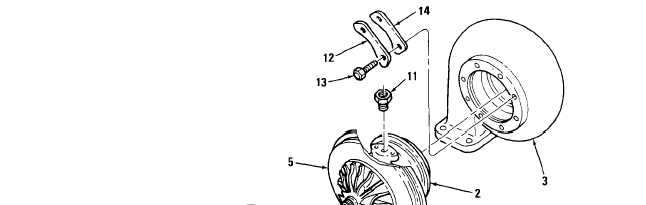
Aline match marks on turbine housing (3) with marks on center housing (2). Secure with four
clamps (14), four locking plates (12), and eight bolts (13). Apply antiseize compound to bolts
(13). Torque bolts to 100-130 lb-in (11-15 N-m) and bend locking plate tangs over side of
bolt heads.
Aline match marks on compressor housing (1) with marks on center housing (2). Secure
compressor housing to backplate (5) with V-band clamp (4). Lubricate threads on toggle bolt
with engine oil and torque nut on toggle bolt to 110-130 lb-in (12-15 N-m).
Install adaptor bushing (11) in oil inlet hole in center housing (2).
NOTE
On model 7083-7396, install angle bracket (9) with bolt (6) away from turbine inlet.
(24) Install gasket (10), oil drain tube (8), two Iockwashers (7), and two bolts (6) on oil outlet of
center housing (2). Torque bolts to 30-35 Ib-ft (41-47 N-m).
END OF TASK
FOLLOW-ON MAINTENANCE
Para Description
4-2
Turbocharger removed (7083-7395)
5-2
Turbocharger removed (7083-7396)
C h a n g e
1
4-183
|
|