TM 9-2815-202-34
(1) Clean all parts with dry cleaning solvent and dry with compressed air. Inspect all parts.
(2) Inspect all bearings and shafts for corrosion, pitting, rough spots, and excessive wear.
(3) Inspect governor housing and cover for cracks, warpage, and damaged threads.
(4) Inspect governor weights after assembly for free movement.
c. Assembly
(1)
(2)
(3)
(4)
(5)
(6)
(7)
(8)
(9)
(10)
(11)
(12)
For model 7083-7395 only, install
starting aid screw (93) through inside
of governor housing (3) and secure
with nut (94) on outside of governor
housing.
If removed, install pin (66) in
operating lever (68).
Install adjusting screw (92) and
locknut (91) in operating lever (68).
Coat inside diameter of operating
shaft upper bearing (90) with engine
oil. Using an arbor press, install upper
bearing (90), numbered side up, on
large end of operating shaft (85).
Using an arbor press, install
operating lever (68), with pin (66)
facing up, onto operating shaft (85),
alining flat on lever with flat on shaft,
until flush with operating shaft (85).
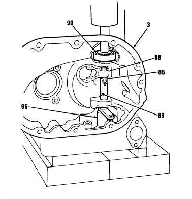
Install spacer (89) onto operating shaft (85).
Insert end of governor operating shaft (85), bearing (90), spacer (89), and operating lever
(68) through upper bearing bore in governor housing (3) with operating fork (88) facing rear
of governor housing.
Place governor housing (3) in arbor press with top facing down.
Place a support (95) under operating shaft (85) and press operating fork (88) until spacer
(89) does not move up or down.
Lubricate operating lever bearing (90) with engine oil and seat bearing in governor housing
(3). Install screw and washer assembly (83), and washer (84) to secure bearing.
Lubricate lower bearing (86) with engine oil and start bearing into governor housing (3) on
operating shaft (85).
Place a 7/16 inch inside diameter sleeve on inner race of lower bearing (86). Using arbor
press, install bearing on operating shaft (85) until bearing seats on shoulder in governor
housing (3).
4-255
|
|


