TM 9-2815-225-34&P
3-92. ENGINE DYNAMOMETER TESTING (Contd)
LOCATION/ITEM
ACTION
REMARKS
e. Final Check (Contd)
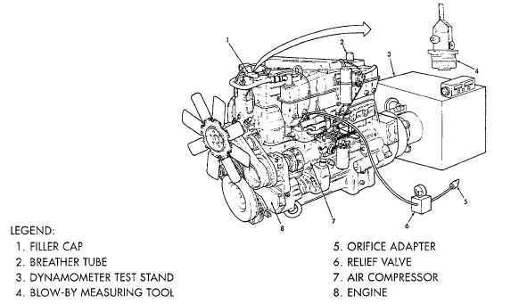
16. Orifice adapter (5) and
Remove from air compressor
air compressor (7)
relief valve (6).
17. Blow-by measuring tool (4)
Remove from engine (8) and
and manometer
install filler cap 1).
18. Breather tube (2)
Unplug.
NOTE
At each phase, record crankcase pressure (blow-by), engine speed, and load at one minute
intervals. Watch for increases or wide shifts in blow-by pressure. If sudden increase
happens, or if it is more than 12" H2O, do the preceding test over again and run engine 15
more minutes. When blow-by is OK, do next test. If not OK, stop the test and find reason
for too much blow-by. Check engine for fuel, oil, water, air, or exhaust leaks after each test
and fix as needed.
Phase 1 - 25% HP @ 1200 RPM @ 160 water temperature.
Phase 2 - 40% HP @ 1200 RPM
Phase 3 - 65% HP @ 1600 RPM
Phase 4 - 100% HP @ Nominal torque peak RPM *(1200) RPM
Power Check - 96-100% HP @ 1600 RPM
*100 RPM below torque peak RPM
FOLLOW-ON TASK:
Perform on-engine fuel pump adjustment (para. 3-93).
Table 3-1. Dynamometer Test Chart
ENGINE HP @ RPM
RATED
HP @ RPM
500 FT-ALT
FUEL
RATE
LB/HR
AIR MANIFOLD
PRESSURE
IN/HG
ALTITUDE
MAX. HP
ALT.
CRANKCASE
PRESSURE
W/TURBO T46B
PHASE 1
TO 160f
HP @ RPM
PHASE 2
2 MIN.
HP @ RPM
PHASE 3
5 MIN.
HP @ RPM
PHASE 4
4 MIN.
HP @ RPM
POWER
CHECK
4 MIN.
HP @ RPM
NTC
400
400 @
2100
400 @
2100
139-145
39/47
12,000
12" H2O
100 @
1200
160 @
1200
260 @
1600
Full Load
@ 1200
384 @
2100
3-689
|
|