
| Tweet |

Custom Search
|
|

|
||
 TM 9-8000
b. Ignition System. The ignition system (chapter
the cam lobe pushes up on the lifter, it will in turn push
the valve open against the pressure of the spring. In
15) ignites the fuel and air mixture in the combustion
view D, the cam lobe has passed the center of the lifter
chamber at the precise moment needed to make the
bottom. As it rotates away from the lifter, the valve
engine run.
spring pulls the valve closed.
c. Cooling System. The cooling system (chapter
By proper positioning of the cam lobes on the camshaft,
9) removes the excess heat from the engine that is
a sequence can be established for the intake and
generated from combustion.
exhaust valves. It is demonstrated in paragraphs 2-5
thru 2-8 that the intake valve and the exhaust valve must
d. Lubrication System. The lubrication system
each open once for every operating cycle. As explained
(chapter 8) provides a constant supply of oil to the engine
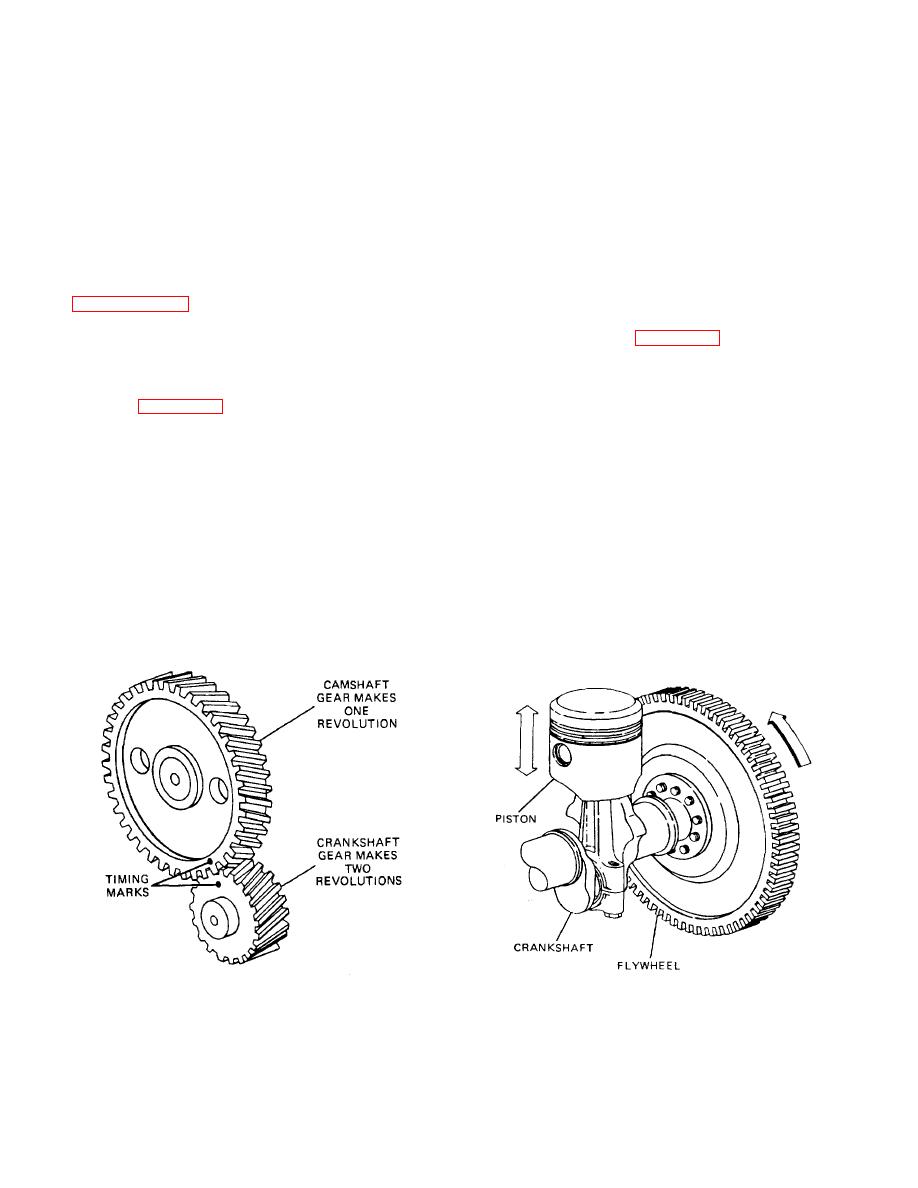
in paragraph 2-4, the crankshaft must make two
to lubricate and cool the moving parts.
complete revolutions to complete one operating cycle.
Using these two facts, a camshaft speed must be exactly
e.
Flywheel (Fig.
As discussed in
one-half the speed of the crankshaft. To accomplish this,
paragraphs 2-5 thru 2-8, for every two revolutions that
the timing gears are made so that the crankshaft gear
the crankshaft makes, it only receives one power stroke
has exactly one-half as many teeth as the camshaft gear,
lasting for only one-half of one revolution of the
as shown in figure 2-10. The timing marks are used to
crankshaft. This means that the engine must coast
put the camshaft and the crankshaft in the proper
through one and one-half crankshaft revolutions in every
position to each other.
operating cycle. This would cause the engine to produce
very erratic power output. To solve this problem, a
2-10. Engine Accessory Systems.
flywheel is added to the end of the crankshaft. The
flywheel, which is very heavy, will absorb the violent
thrust of the power stroke. It will then release the energy
a. Fuel System. The fuel system (chapter 4)
back to the crankshaft so that the engine will run
supplies the engine with a properly proportioned fuel and
smoothly.
air mixture. It also regulates the amount of the mixture to
the engine to control engine speed and power output.
Figure 2-10. Timing Gears
Figure 2-11. Flywheel
2-7
|
||
|
||


