
| Tweet |

Custom Search
|
|

|
||
 TM 9-8000
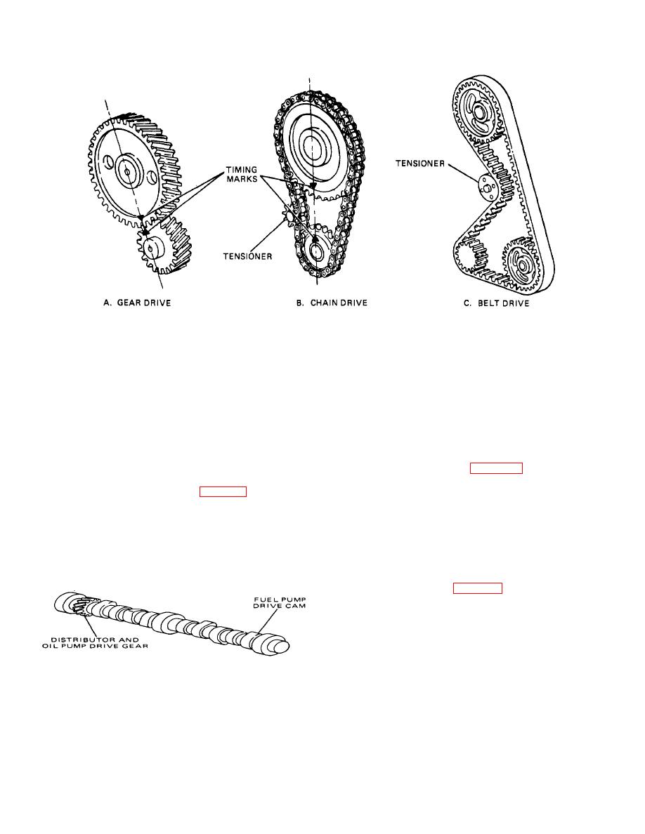
Figure 3-53. Driving the Camshaft.
crankshaft must rotate twice as fast as the camshaft, the
camshaft to operate the pump. On diesel engines, the
drive member on the crankshaft must be exactly one-half
camshaft often Is utilized to operate the fuel Injection
as large as the driven member on the camshaft. In order
system.
for the camshaft and crankshaft to work together, they
h. Tappets. Tappets (or lifters) are used to link the
must be In the proper Initial relation to each other. This
camshaft to the valve mechanism. The bottom surface Is
Initial position between the two shafts Is designated by
hardened and machined to be compatible with the
marks that are called timing marks. To obtain the
surface of the camshaft lobe. The following are the two
correct Initial relationship of the components,
the
basic lifter classifications:
corresponding
marks
are aligned at the time of
assembly.
solid) lifters are simply barrel-shaped pieces of metal.
g. Auxiliary Camshaft Functions (Fig. 3-54).
When used In flathead engines, they have an adjusting
The camshaft, after being driven by the crank-shaft, In
screw mechanism to set the clearance between the
turn drives other engine components. On gasoline
tappets and the valve stems. Mechanical tappets may
engines, the oil pump and the distributor usually are
also come with a wider bottom surface. These are called
mushroom tappets. Another variation Is the roller tappet,
driven from a common gear that Is machined Into the
which has a roller contacting the camshaft. They are
camshaft. The fuel pump Is also driven by the camshaft.
used mostly In heavy-duty applications to reduce
This usually Is accomplished by machining an extra lobe
component wear.
on
the
Is very popular In overhead valve engines. It uses oil
under pressure to automatIcally maintain zero clearance
In the valve mechanism. The lifter body, which contacts
the camshaft lobe, Is hollow. Inside the lifter body, there
Is a plunger that operates the valve mechanism. Injecting
oil into the cavity under the
TA233381
Figure 3-54. Auxiliary Camshaft Functions.
3-31
|
||
|
||


