| Tweet |

Custom Search
|
|

|
||
 TM 9-8000
create correct gage readings. An example would be a
poles on the gage pointer will be positioned midway
one-quarter full fuel tank. At this level, the tank unit would
between the coils. When the armature is in this position,
divide the voltage so that 75 percent of the current would
the pointer will indicate a full reading.
flow through the right-side strip and 25 percent would
flow through the left-side strip. This would produce a
(3) Variations in electrical system voltage will
one- quarter gage reading.
affect both magnetic coils equally and, therefore, will not
upset the differential created between them. Because of
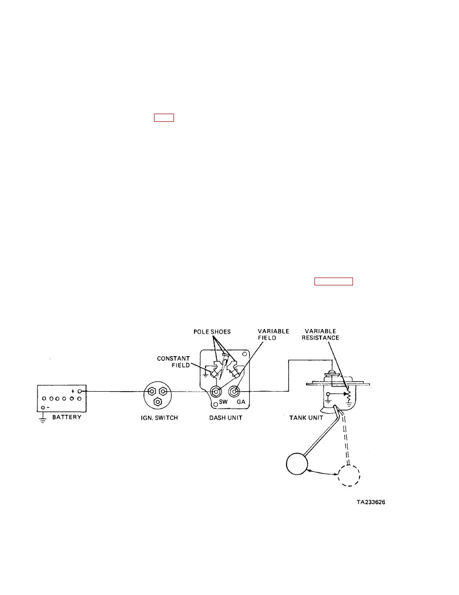
d. Magnetic Fuel Gage (Fig. 17-9). The basic
this, the magnetic gage is self-regulating and requires no
voltage- limiting devices.
instrument panel gage consists of a pointer that is
mounted on an armature. Depending on the gage
(4) The magnetic gage is very sensitive to road
design, the armature may contain either one or two
shock and sudden changes in voltage such as those
poles. The gage is motivated by a magnetic field that is
caused by the fuel sloshing in the tank. Because of this,
created by two separate magnetic coils that are
the armature of the instrument panel gage will be fitted
contained within the gage. One of these coils is
with a damping device or a flywheel.
connected directly to the battery, producing a constant
magnetic field. The other coil produces a variable field
whose strength is determined by a rheostat-type tank
17-4. Pressure Gages.
unit whose operation is the same as the one described in
paragraph 17-3b. The coils usually are placed 90
a. Usage. Pressure gages are used widely in
degrees apart.
automotive applications to keep track of things such as
engine oil pressure, fuel line pressure, air brake system
(1) When the tank is empty, the tank unit creates
pressure, and the pressures of the hydraulic systems in
a very high resistance. This causes the variable
special purpose vehicles. Depending on the equipment,
magnetic coil to produce almost no magnetic field.
a mechanical or an electric pressure gage may be
Therefore the armature poles on the gage pointer will be
utilized.
attracted to the constant magnetic coil. The pointer will
point to empty when the armature is in this position.
b. Electric Gage (Fig. 17-10). The instrument panel
gage may be of the thermostatic type described in
(2) When the tank is full, the tank unit will create
paragraph 17-3a, or of the magnetic type described in
no
Therefore,
the
armature
paragraph
17-3d.
The
sending
Figure 17-9. Magnetic Fuel Gage
17-7
|
||
 |
||