| Tweet |

Custom Search
|
|

|
||
 TM 9-8000
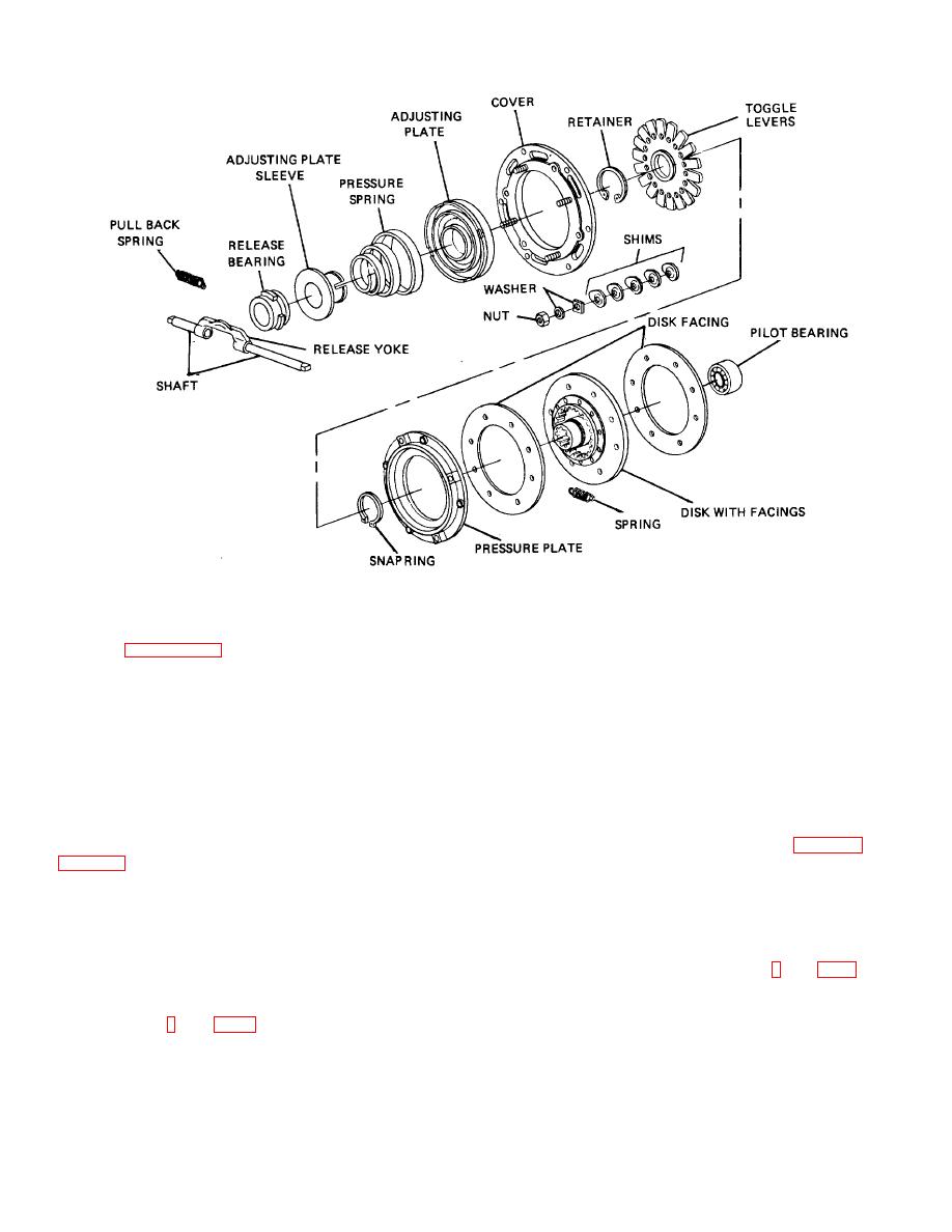
Figure 21-3. Single, Large Coil Spring Clutch.
shown in figures 21-5 and 21-6. In the helical-spring
an engaged position. The releasing of the clutch is
clutches, a system of levers pivoted on the cover forces
accomplished through the use of a lever-type fork. The
the pressure plate away from the driven disk and against
clutch, because it is a rotating member, requires that the
the pressure of the springs whenever the clutch release
fork release it through a release bearing that keeps the
bearing moves forward against the inner ends of the
fork from rubbing directly on the clutch. The fork is
activated by the operator through either a mechanical or
holds the plates in contact. In diaphragm clutches, the
hydraulic operating system.
dish-shaped diaphragm performs the same function. The
clutch release (or throwout) bearing is a ball-thrust
bearing contained in the clutch
release
bearing
housing, or collar, mounted on a sleeve attached to the
b. Mechanical _ Operating System (Fig. 21-8). The
front of the transmission case. The release bearing
mechanical clutch operating system Is the most
clutch, and is moved by the release yoke to engage the
common. One type of system uses mechanical rod-type
release levers and move the pressure plate to the rear,
linkage while another type uses a flexible cable.
thus separating the clutch driving members from the
driven member when the clutch pedal is depressed by
the driver.
c. Hydraulic Operating System (Fig. 21-9). The
hydraulic clutch operating system moves the fork by
21-3. Clutch Operating Systems.
hydraulic pressure. Movement of the pedal creates
pressure in the master cylinder, which actuates the slave
a. General (Fig. 21-7). The automotive clutch,
cylinder. The slave cylinder then moves the clutch fork.
through spring pressure, normally is In
TA233675
21-3
|
||
 |
||