
| Tweet |

Custom Search
|
|

|
||
 TM 9-8000
Section V. DUMP TRUCK MECHANISMS
box, and the power takeoff. The body control box
contains two cams that move as the control lever is
body that pivots at the rear. The dump body pivots on
moved; this causes the dump body to raise, hold, or
two hinge pins when it is raised by a hydraulic hoist
lower, according to the control lever position.
cylinder mounted on a transverse base shaft. The
pressure developed in the hydraulic hoist cylinder by the
36-19. Dump Body Control Lever (Fig. 36-15). The
operation of a special pump causes the dump body to
move up into the position shown in figure 36-13. Since
dump body control lever, located in the cab, has four
the hydraulic cylinder is double acting, it also is used to
positions. In position A, the body is down and the power
hold or lower the dump body. The endgate (fig. 36-14)
takeoff is disengaged. When the control lever is moved
normally is pivoted at the top, and is secured in this
to position B, the forward arm in the control box is
position by lockpins through endgate upper latches.
engaged and the shift linkage engages the power
Lower latches hold the endgate closed until they are
takeoff. To raise the body, the control lever is moved
released by the hand lever on the front left corner of the
forward past position C to position D. The lift can be
body. The endgate is released for dumping in this
stopped and the body held in any position by returning
manner, and the extent that it opens is controlled by
the control lever to position C. With the lever at position
adjustment of the chains in the locking slots (fig. 36-14).
B or D, the body is automatically checked at either the up
or down position at the limit of travel.
36-18. Body Control Box. A dump body control lever
36-20. Control Valve and Pump. When the power
in the rear and at the left of the driver's seat operates a
shift control lever connected by linkage to a control box.
takeoff is engaged, the pump is driven. It can now
deliver hydraulic fluid to the hydraulic cylinder, _provided
shows the linkage between the control lever, the control
the control valve is properly positioned. The control valve
is linked to the control lever (fig. 36-15). When the
control lever is moved to position D, the control valve
directs the hydraulic
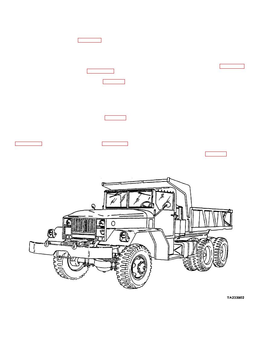
Figure 36-12. Dump Truck - Side View.
36-9
|
||
|
||


